

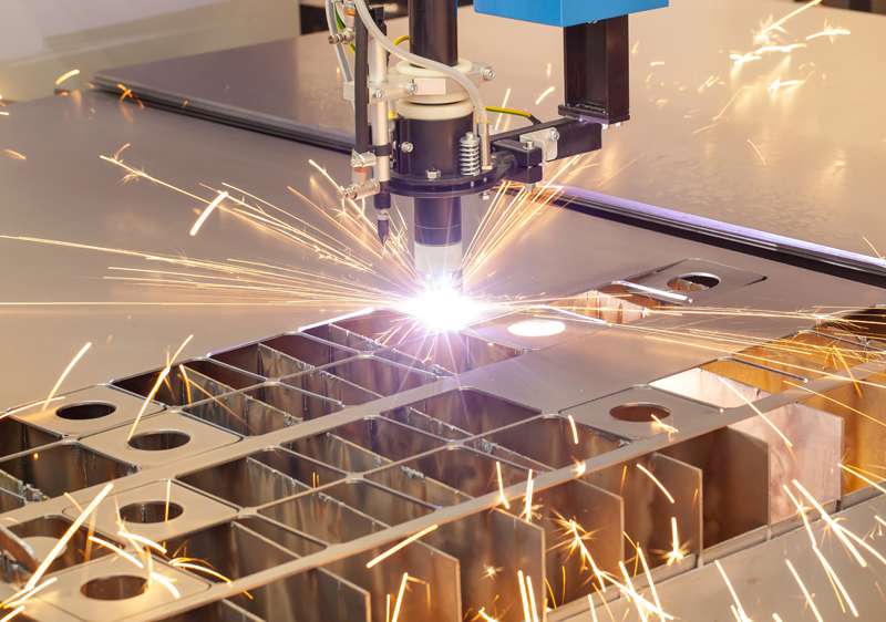
Thermal cutting technologies represent the primary gateway for processing raw flat sheet and plate materials into foundational components across structural, industrial, and heavy machinery manufacturing. Before plate metal can be formed on a press brake, stamped in a die, or welded into complex assemblies, it must be profiled with high positional accuracy and clean cut-edge characteristics. Modern thermal processing relies on three primary energy sources: focused high-power photon beams (fiber and CO2 lasers), high-velocity ionized gas jets (plasma arc cutting), and exothermic iron-oxygen chemical reactions (oxy-fuel cutting).
Selecting the appropriate thermal profile method requires balancing material type, plate thickness, dimensional tolerance thresholds, edge geometry requirements, heat-affected zone (HAZ) limits, and operational cost efficiency. Understanding the complete lifecycle of thermal cutting involves examining thermal beam-material interaction dynamics, assist gas fluid mechanics, CNC motion control integration, metallurgical heat impacts, and quality assurance metrics.
1. Laser Beam Cutting Dynamics: Fiber vs. CO2 Optics
Laser cutting directs a concentrated, high-density beam of coherent monochromatic light onto a metal substrate. The absorbed optical energy rapidly elevates the material’s surface temperature past its melting or vaporization point, while a co-axial high-pressure assist gas jet expels the molten metal down through the cut kerf.
CO2 Laser Systems
CO2 lasers generate a laser beam inside a gas mixture of carbon dioxide, nitrogen, and helium excited by radio-frequency or electrical discharge. The resulting light has a wavelength of 10.6 micrometers. The beam is routed to the cutting head through a series of external water-cooled gold or silicon mirrors inside enclosed beam delivery tubes.
While 10.6-micron optics provide exceptional cut-edge smoothness on thick carbon steel plates and organic materials, the wavelength is poorly absorbed by highly reflective non-ferrous metals like copper, brass, and aluminum. Furthermore, optical mirror alignment requires regular maintenance, and the overall electrical-to-optical wall-plug efficiency remains relatively low (typically 10% to 12%).
Fiber Laser Systems
Fiber laser technology utilizes solid-state laser diodes to pump ytterbium-doped optical fiber cores, generating a laser beam with a wavelength of approximately 1.07 micrometers. The beam is delivered directly to the cutting head via a flexible armored fiber-optic cable, eliminating the need for complex external turning mirrors and alignment optics.
Fiber lasers offer major operational advantages over CO2 systems:
-
Wavelength Absorption: The 1.07-micron wavelength is absorbed by reflective metals at rates three to four times higher than CO2 radiation, enabling fast, stable cutting of copper, brass, aluminum, and stainless steel.
-
Energy Efficiency: Fiber lasers achieve wall-plug efficiencies between 35% and 50%, drastically reducing electrical power requirements.
-
Processing Speed: On thin-to-medium gauge sheet metal (under 6 mm), fiber lasers deliver cutting speeds several times faster than equivalent-wattage CO2 systems.
Beam Focus Optics and Kerf Dynamics
The laser head focuses the raw beam down to a microscopic focal spot—typically 0.05 mm to 0.3 mm in diameter—generating power densities exceeding millions of watts per square centimeter. The relative position of this focal point relative to the material surface is critical:
-
Focal Point On Surface: Used for thin materials to achieve maximum power density and narrowest kerf width.
-
Focal Point Above Surface: Applied during high-pressure nitrogen cutting of stainless steel to broaden the kerf channel, allowing assist gas to blast away viscous molten material effectively.
-
Focal Point Below Surface: Utilized for thick carbon steel plate oxygen cutting, creating a wide melt path that prevents the kerf from bridging closed.
2. Assist Gas Fluid Mechanics and Chemical Reactions
The assist gas delivered co-axially through the cutting nozzle tip performs two core functions: mechanically clearing the liquid melt pool from the kerf channel and reacting chemically with the metal substrate.
-
+———————————–+
-
| LASER ASSIST GAS TYPES |
-
+—————–+—————–+
-
|
-
+—————————+—————————+
-
| |
-
+—–+—–+ +—–+—–+
-
| Oxygen | | Nitrogen |
-
| (Reactive)| | (Inert) |
-
+———–+ +———–+
-
• Exothermic reaction with iron • Purely mechanical ejection
-
• Low gas pressure (0.5 to 2 bar) • High gas pressure (10 to 25 bar)
-
• Forms dark oxide layer on edge • Produces bright, oxide-free edge
-
• Ideal for thick carbon steel • Essential for stainless & aluminum
Oxygen Cutting (Reactive Cutting)
Oxygen assist gas reacts exothermically with iron in carbon steel. The chemical reaction generates supplemental thermal energy, aiding the laser beam in melting thick steel plates at lower beam power settings and modest gas pressures (0.5 to 2 bar). However, this exothermic reaction leaves a dark iron oxide scale along the cut edge. If left untreated, this oxide layer prevents protective paints or powder coatings from adhering properly, requiring secondary chemical or mechanical de-scaling.
Nitrogen Cutting (Inert High-Pressure Cutting)
Nitrogen is an inert gas that does not react chemically with the molten metal. It functions as a mechanical piston, using extreme kinetic energy (delivered at pressures between 10 and 25 bar) to blast the molten material out of the cut zone. Because no oxidation occurs, nitrogen cutting produces a bright, clean, oxide-free edge. This edge can be painted or welded immediately without secondary surface treatment, making it the standard method for stainless steel, aluminum, and high-spec structural brackets.
Compressed Air Cutting
High-purity, oil-free dried compressed air (consisting of 78% nitrogen and 21% oxygen) serves as an economical middle-ground assist gas for thin carbon steel and sheet metal enclosures. While it introduces light edge oxidation, it delivers high processing speeds at a fraction of the cost of bottled liquid nitrogen.
3. High-Definition Plasma Arc Cutting (HD-PAC) Mechanics
Plasma cutting transforms an electrical gas stream into a high-velocity, ionized plasma state capable of reaching temperatures exceeding 20,000°C (36,000°F). While lasers dominate thin sheet metal profiling due to their precision, plasma arc cutting remains a cost-effective solution for medium-to-heavy metal plate applications (ranging from 6 mm to over 50 mm in thickness).
Plasma Arc Generation Sequence
-
Pilot Arc Phase: High-voltage, high-frequency electrical pulses create a small pilot arc between an internal tungsten cathode electrode and the surrounding copper nozzle tip inside the torch head.
-
Transferred Arc Phase: As the torch approaches the conductive metal plate (the anode), the main power supply initiates a transferred arc. Current flows directly from the internal electrode through the ionized gas stream and into the grounded metal workpiece.
-
Constriction and Shielding: Swirling dual-gas or water-shrouded nozzles compress the plasma arc into a tight, highly stable column. Auxiliary shield gases (such as oxygen, nitrogen, methane, or argon-hydrogen mixtures) surround the central arc column to isolate the melt zone from atmospheric contamination and sharpen the edge angle profile.
Modern High-Definition Plasma (HD-PAC) systems utilize specialized, micro-orifice nozzle designs and real-time gas mixing controls. HD-PAC compresses the plasma energy into a tight current density, yielding clean cuts with minimal edge bevel angles (under 2 to 3 degrees), reduced kerf widths, and negligible dross formation compared to older conventional air-plasma cutters.
4. Oxy-Fuel Thermal Cutting for Extreme Plate Thicknesses
For carbon steel plates exceeding 50 mm to 300+ mm in thickness—such as those used in heavy mining machinery, thick pressure vessel flanges, and massive structural baseplates—laser and plasma systems lack the thermal penetration depth required. These extreme applications rely on oxy-fuel cutting.
Oxy-fuel cutting is purely a chemical reaction rather than an arc or optical melting process. The process operates in two distinct thermal stages:
-
Preheating: An inner ring of flame nozzles burning a mixture of oxygen and fuel gas (such as acetylene, propane, or natural gas) heats the steel surface to its ignition temperature—approximately 870°C (1,600°F), where the steel glows bright red.
-
Oxidation Jet: Once the ignition temperature is reached, a central high-purity oxygen jet opens. The high-pressure oxygen streams directly into the heated spot, triggering a rapid, self-sustaining exothermic combustion reaction that converts the solid iron into molten iron oxide ($Fe_3O_4$). The momentum of the oxygen stream blows the liquid slag out the bottom of the plate, advancing the cut channel.
Because non-ferrous metals like aluminum and stainless steel do not undergo this exothermic oxidation reaction with iron, oxy-fuel cutting cannot process non-ferrous materials.
5. Heat-Affected Zone (HAZ) and Metallurgical Impacts
All thermal profiling techniques introduce concentrated heat into the parent metal, creating a narrow region adjacent to the cut edge known as the Heat-Affected Zone (HAZ). Although the metal within the HAZ does not melt, its internal microstructural grain phase is altered by rapid heating and subsequent quenching from the cold surrounding plate.
-
MICROSTRUCTURAL ZONES ALONG A THERMAL CUT EDGE
-
-
+——————-+——————–+——————–+
-
| Melt / Kerf | Heat-Affected Zone | Unaffected Parent |
-
| Channel | (HAZ) | Base Metal |
-
+——————-+——————–+——————–+
-
| Rapidly solidified| Phase changes occur| Original grain |
-
| oxide/slag edge | (e.g., Martensite) | structure retained |
-
| | Hard & Brittle | Ductile & Malleable|
-
+——————-+——————–+——————–+
Metallurgical Changes in the HAZ
-
Grain Growth and Microhardness: In carbon and alloy steels, rapid heating past the phase transformation temperature followed by fast conductive heat sinking into the bulk plate creates a localized, ultra-hard martensitic grain structure. This hardened edge exhibits reduced impact toughness and high residual tensile stress.
-
Micro-cracking and Bending Failures: If a thermal-cut component with a hardened HAZ undergoes severe secondary press brake bending directly along the cut line, the brittle HAZ edge can develop micro-cracks that propagate into full structural tears.
-
Intergranular Corrosion in Stainless Steels: In stainless steels, unmanaged heat input in the HAZ causes chromium to react with carbon, forming chromium carbides along grain boundaries (sensitizing the metal). This depletes local chromium levels below the 10.5% threshold required for corrosion resistance, leaving the HAZ vulnerable to intergranular corrosion.
Laser cutting generates the narrowest HAZ (typically under 0.1 mm to 0.3 mm) due to its localized energy input and rapid travel speeds. Plasma cutting produces a wider HAZ (0.5 mm to 1.5 mm), while oxy-fuel creates the largest HAZ (frequently exceeding 2 mm to 5 mm) due to its high overall heat input and slow linear cutting speeds.
6. CNC Motion Control, Nested Layouts, and Quality Metrics
To convert flat plate into finished parts efficiently, cutting heads are mounted on multi-axis CNC gantry motion systems. Advanced CNC cutting machine beds incorporate down-draft multi-zone exhaust tables that open vacuum dampers directly beneath the active cutting head, pulling toxic fumes, metal dust, and thermal smoke down into filtration systems.
CAD/CAM Nesting Strategies
Prior to cutting, specialized nesting software organizes dozens of individual digital part geometries onto a standard raw metal sheet size (such as 1.5 m x 3.0 m or 2.0 m x 6.0 m) to maximize material utilization:
-
Common Line Cutting (CLC): Arranges adjacent parts so they share a single continuous cut line, reducing cutting travel distance, saving gas, and raising material yield above 85%.
-
Bridge Cutting and Chain Cutting: Links multiple separate part profiles together into one continuous toolpath, reducing the number of high-stress pierces required.
-
Lead-In and Lead-Out Management: Directs the high-energy initial pierce point slightly outside the final part boundary, ensuring that pierce blowholes, molten spatter, and thermal marks occur in scrap areas rather than on the finished part edge.
ISO 9013 Quality Assessment Metrics
Thermal cut quality is evaluated globally using the ISO 9013 standard, which rates profile accuracy across several key parameters:
-
Perpendicularity and Angularity Tolerance ($u$): Measures the deviation of the cut face from a true 90-degree right angle relative to the plate surface. High-precision laser cuts achieve class 1 or 2 low-bevel angles, while plasma cuts typically fall into class 3 or 4.
-
Mean Surface Roughness ($Rz_5$): Evaluates the height of striation lines formed along the cut face by gas dynamic pulsations. Smooth striation lines reduce fatigue failure risk in dynamically loaded structures.
-
Dross Formation: Evaluates the amount of re-solidified molten metal droplets adhering to the bottom edge of the cut plate. Minimal dross formation eliminates the need for manual secondary grinding operations.
Stainless steel pipes kampala uganda